Yamaha Rhino Forum banner

700 rhino fuel pump not working

52K views 25 replies 6 participants last post by  Rhino2015  
#1 ·
hey guys, i have a 2009 yamaha rhino 700 FI, and for some reason my fuel pump is not coming on when i turn the key on, i have checked the voltage on the 2 plugs that plug in on top of the pump and only one plug is working that runs the fuel gauge, any ideas would greatly be appreciated
 
#2 ·
There is a fuse specifically for the fuel pump. From the wiring diagram, it looks like it is on the starter relay, where the mains fuse was on the 660. If there are 2 fuses there, check both as one is likely to be a spare like it was on the 660.
 
#4 ·
There is a relay involved, presumably in the battery box. The fuse on the starter relay is connected to one of the relay contacts with a Brown/Black stripe wire. The other relay contact is connected to the fuel pump with a Red/bLue stripe wire. The coil of the relay is served by a Brown/Red striped wire (+) and a bLue/Red striped wire (-). Those colors will help you to find the correct relay in the battery box.

I would suggest that you use your voltmeter (with the ignition on) to see if 12V (as measured to ground) is getting to the relay and if it is leaving the relay (via the contact connections). You should also see 12V on the coil of the relay (+) wire.

If there is voltage coming in on the Brown/Black wires and none coming out of the Red/bLue wire, your relay is bad. If you have voltage on all 3 wires then inspect the Red/blue wire and its connections, as you say you are not getting voltage at the far end.
 
#5 ·
ok i checked both the brown wires goin to the fuel pump relay and sure enough they getting fire up to the relay but the red/blue wire going from relay to the pump has nothing, i see there are 3 other relays beside that one are they interchangable? i seen they had the same part numbers on them, so i switched them and it still didnt work
 
#6 ·
If it was a bad relay, swapping for another should have worked. What I would do here is to partially unplug the relay just far enough that the prongs are still making contact with the socket and there is room to get your probe onto the blade that is associated with the Red/bLue wire. If you have voltage there at the blade but not at the wire, it is a bad connection at the connector. That has been known to happen once in a while.

Now, if that does not give you a voltage, there is the low side of the coil (bLue/Red stripe) that goes to the computer for some reason. If the computer is not grounding that wire out or if there is a flaw in the wire or connections the relay would not close I'm assuming at this point that it does not click when you turn the ignition on and off?

To check the grounding of the wire going to the computer, put the red probe on the exposed blade going to the bLue/Red stripe wire and the black probe on ground. With the ignition on the meter should read zero or a very low voltage if the computer is grounding the relay as it should. If it is reading 12V or close to that, it is not being grounded as it should be. It could be a fault in either connector (relay end or computer end).

If you get this far and do not find anything lets get back together and do some slicing and dicing :)
 
#8 ·
hey SteveS i pulled the relay out just enough to get the prong of the voltage meter in there i tested the red/blue wire with the ground wire that runs into the relay then i put the ground prong on the voltage meter to the ground post on the battery and its showing 12 volts both times
 
#9 ·
I'm not clear on exactly what you are saying here: "I tested the red/blue wire with the ground wire that runs into the relay". You had the red probe on the Red/bLue wire and on a ground wire, but what ground wire. There is no ground wire, as such, going to the relay that I see on the wiring diagram. The Red/bLue wire gets pulled to ground by the ECU when the ignition switch is on. Hence you should not be seeing 12V there.

But no matter, you are seeing 12V there and it should be at ground potential. The ECU is not pulling it to ground and logically the only reason they have the ECU involved is to kill the fuel pump when the rig is upside down. So, I believe that the fault lies the lean angle sensor.

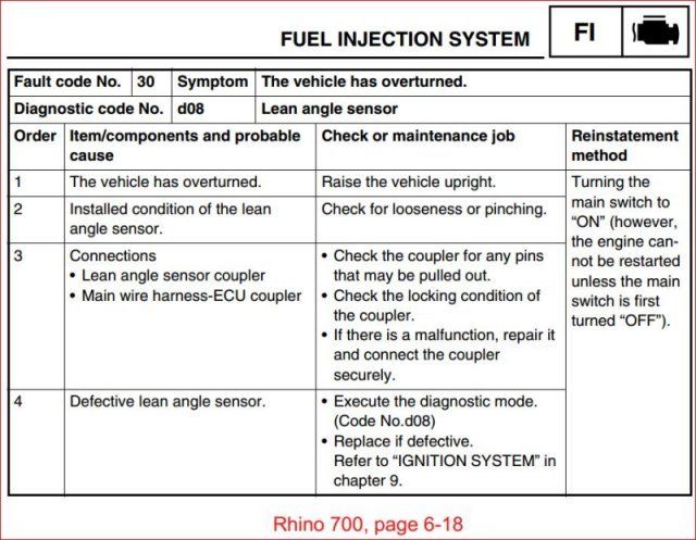
If you launch a diagnostic run on the ECU through the digital dash, you may be able to reset it. This is way above my knowledge as to how to do it. here is the page out of the manual. I hate these "one button computers", worse than an Apple tablet!

Image


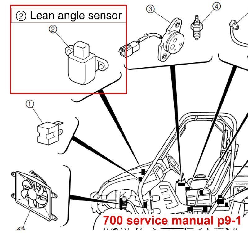
Location of the Lean angle sensor per Yamaha's Wonderful diagraming. I'm guessing somewhere near, or in, the battery box? The picture is good for recognizing it after you find it....

Image


If the lean angle switch is bad, here are some snips out of long forgotten sources as to the details on what should be happening and ways of "locking" the switch. I believe that I have an easier way to defeat it, see the last comment down at the bottom.

Quote:

Originally Posted by g660
Like stated by others it is a issue with the grizzly's. I read a lot about the problems with them and read articles of how others were filling it with glue and such. Just thought I would let others know a different way. And, don't take this the wrong way, but most experienced riders know what to do when a bike rolls over and knows how to control a bike for any other bypasses that are done. These bike have these safety features for the inexperienced riders IMO!

In my 20+ years of riding, The rollovers i have seen were mostly by experienced riders. Flying through unknown terrain and hitting a rock, taking on questionable hills etc.
As far as flipping the kill switch at that fraction of a second that you have to react. all i can say is good luck.
Not only is the sensor a safety factor, it also protects the engine from running without oil while upside down or on its side.


Quote:

Originally Posted by Mccdan
Same reason why people remove the brake interlock on the shifter, the reverse speed over ride etc. etc. If you feel comfortable making your own decisions about what the machine is doing rather than have the machine make those decisions for you. There's already a means to kill the engine on the left and right side of the quad. The kill switch and the ignition key. For a lot of us, that's enough. Also as Ole Nasty pointed out; removing a potential liability and one that would be very hard to diagnose on the trail gives us some peace of mind.

How is it a liability and hard to diagnose?
The sensor has three wires.
1-5 volt reference from ECM.
2-Signal return to ECM
3-Ground
AS long as the ECM sees more than 3.5 volts., the engine will run.
when tipped beyond 65 degrees the voltage is pulled down. Anything below 1.35 volts will shut down the engine.
For diagnosis and temporary fix, just disconnect and jumper the 5 volt and signal return. it will get you back on the trail until you can make the repair.
Do what you wish.
I am pointing out that my safety and the cost of major engine repairs are critical to me.
I want to mention that Carbureted engines will most likely shut down themselves pretty quickly.

I found this on a grizzly site authored by (overhill,Feb 13,2015)
Some riders will fill the sensor with glue to defeat the safety feature and others have the modified the switch it self.

If the reset fails, or whatever, and you do not mind over-riding the dubious safety feature: Cut the Red/bLue wire and tie a wire from the relay side end of the wire to ground. This will make the relay work no matter what the ECU is thinking.
 
#10 ·
Another thought: Apparently a tipping event, real or "imaginary", sets the ECU to a "do not run" mode. Supposedly turning the ignition key off and then back on resets the ECU to be able to start again. It is a sure bet that you have done this numerous times.

Assuming that the Lean angle sensor is not actually failed: There is a line that powers the ECU directly from the battery through a fuse called "Backup". This is there to keep the memory within the ECU alive while not running. My thought is that if you unhook the negative ground cable from the battery and let it sit for a long while, it might drop that event out of the memory stores.
 
#11 ·
on the diagram you showed me in the last messege, it says "fault code 30, lean sensor" if it was the lean sensor i would be getting error code 30 on my dash right?? the only code its showing is error code 46, i unhooked the negative battery cable so im letting it sit for a wile now
 
#12 · (Edited)
I'm not sure what code 46 is. I have no smarts in my machine; dumb is good because they obey better and do not have a mind of their own :)

It could be that the display can only show one error code at a time?

If you want to cut that bLue/Red wire and ground it, it very likely will make your fuel pump run. What I don't know here is: Is it the lean angle sensor, or some other thing happening in the ECU. I also don't know until you try it, if any other vital functions (such as ignition, etc.) are not working as well.
 
#14 ·
Makes no sense to me, but the last few days I have been having the same issue. Got power everywhere but fuel pump plug. I also had error 46. Long story short I found a wire on my fuel relay that was corroded bad enough that a slight tug test, it seemed tight. When I removed the relay again it popped out. Jimmy rigged a connector in there and my rhino fired up. Also have a 2009 rhino 700 FI. Hope this helps
 

Attachments

#16 ·
well ive checked all the connections and grounds and everything is tight like it supposed to be but im getting voltage all the way up to the ECU, its just not getting voltage from the ECU to the fuel pump. would the ECU be the problem maybe?
 
#17 ·
The ECU should be pulling the wire to ground. It does not "give" any voltage there. With no ground the pump does not run, ground the wire then the pump runs.

As I said before, I suspect that the ECU is performing a safety function such that the pump is not running. Cutting the wire and grounding the relay side will make the pump run (without the safety function). The pump will still shut off when you turn the ignition key to the off position.
 
#19 · (Edited)
There is a bLue/Red wire running from the relay to the ECU, right? Cut it somewhere along it's length and you will have 2 loose ends, right? Splice a wire onto the loose end that goes to the relay and connect it to ground. Put a bit of insulation on the loose end that goes to the ECU and just leave it be. Is that clear enough?
 
#21 ·
hey steve, i got the fuel pump to come on, i cut the red/blue wire between the relay and ECU and hooked the wire coming from the relay to a toggle switch and connected it to the positive post on the battery and it came on, but the check engine light is on now and its showing error code 43 and 46, is that something i need to worry about or will it be ok??
 
#22 ·
i couldnt get it to come when i turned the ignition switch on, which im not that good of electrician lol, but when i hooked the red/blue wire to the positive post on the battery the fuel pump automatically came on with the ignition switch off so i put the toggle switch on it so i could turn it on/off
 
#23 · (Edited)
You are not doing what I said at all. The positive terminal of the battery is NOT GROUND!

I misstated the wire that you need to mess with midway through this dialog. The wire that you need to cut and ground is the bLue/Red stripe wire (NOT Red/bLue), I have gone back and corrected those entries above. Opposite body color/stripe color combinations are easy to get backwards when you are not looking at the schematic. Sorry about that.

So I will state it again, correctly this time:

Reconnect the Red/bLue stripe wire ends back together again.

There is a bLue/Red wire running from the relay to the ECU. Cut it somewhere along it's length and you will have 2 loose ends. Splice a wire onto the loose end that goes to the relay and connect it to GROUND. Put a bit of insulation on the loose end that goes to the ECU and just leave it be.
GROUND is battery NEGATIVE.

The frame is a ground point as well, IF IT IS ELECTRICALLY CONNECTED to the main welded portion of the frame, which is indeed connected to the battery negative terminal. But beware that not all black painted steel parts that might look like the frame are welded onto the main part of the frame. A black painted steel part may be simply bolted on, painted surfaces to painted surfaces. The paint insulates that metal part from the grounded portion of the frame and it will not work as an electrical ground.
 
#25 ·
I am also having trouble with my fuel pump on my 2015 700 Grizzly. It doesn't pump but I have 4 volts to both center prongs on the plug to the pump. Checked all the fuses and swapped relays back and fourth and still nothing. Not sure if the 4 volts is what is suppose to be at the pump or if it should be 12 and no one at the dealer or service department seems to know or prefers not to tell me so I bring it in to fix.

If anyone knows how to properly test the fuel pump it would be greatly appreciated.

Thanks